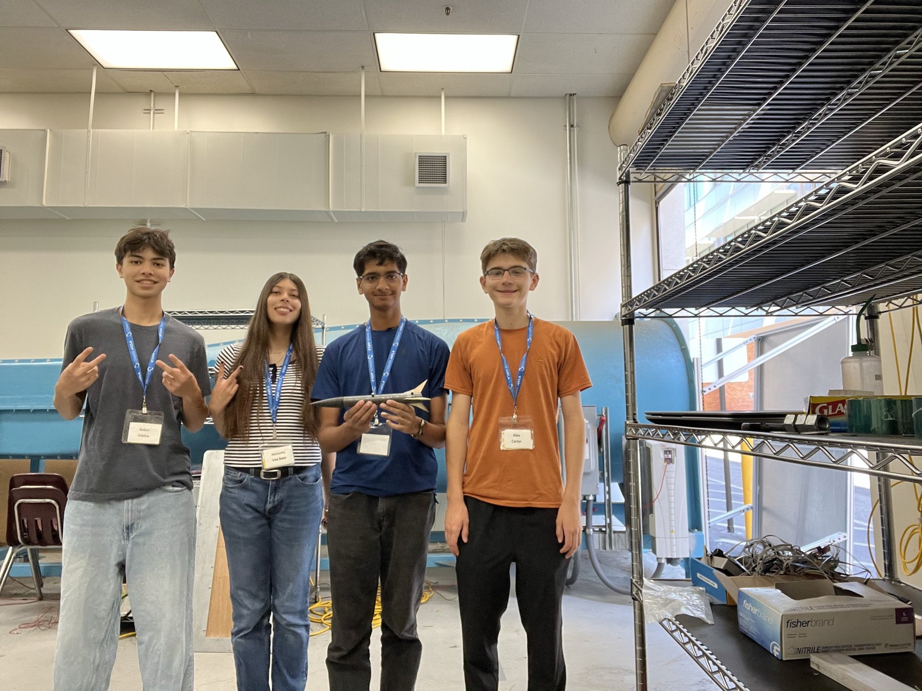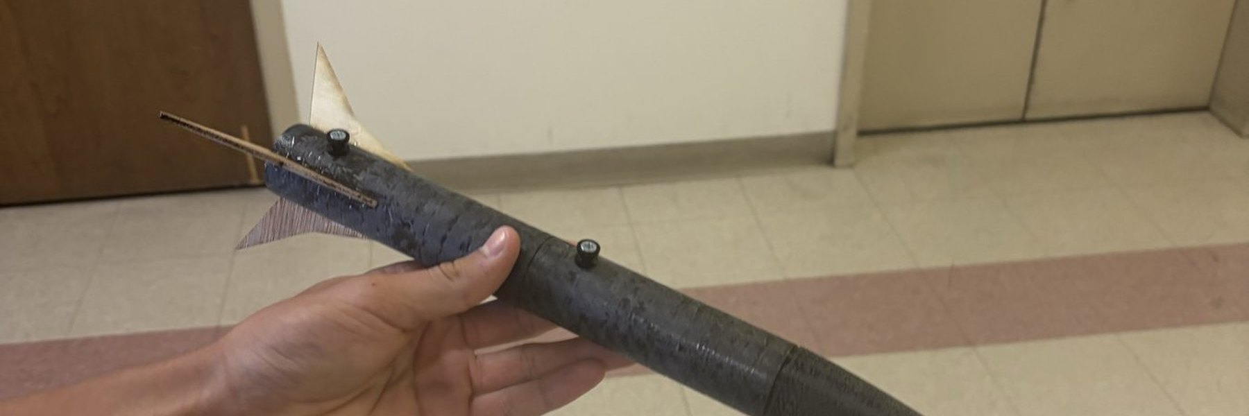
A single-stage rocket we built in two weeks at UCLA that took a 1 oz quail egg to 950 ft and brought it back in one piece.
Overview
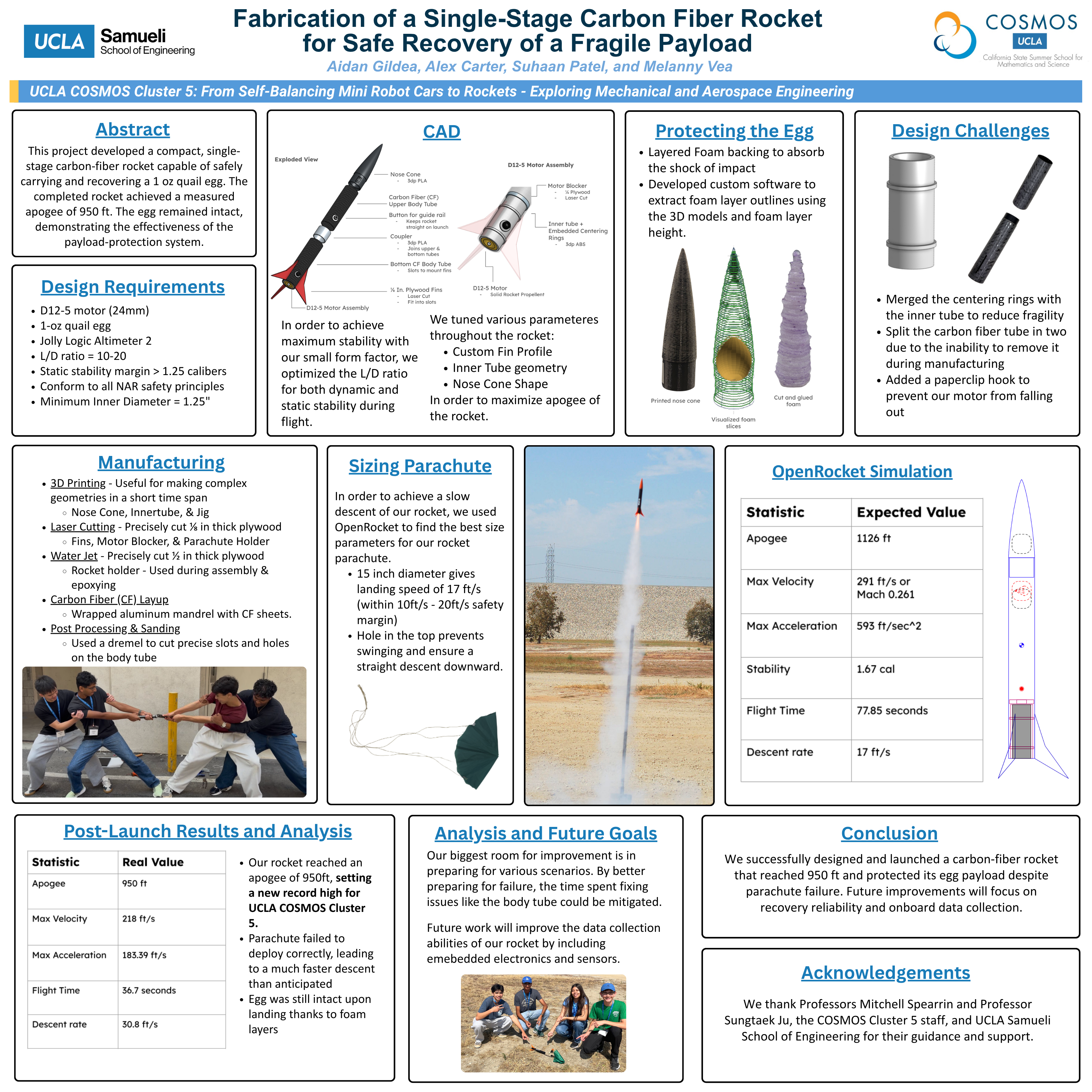
This summer I participated in UCLA COSMOS Cluster 5: From Self-Balancing Mini Robot Cars to Rockets: Exploring Mechanical and Aerospace Engineering. In the first two weeks of this program, our mission was to design, manufacture and launch a rocket to a set of specific design parameters.
- Estes D12-5 motor (24 mm)
- 1 oz quail egg as the payload
- Jolly Logic AltimeterTwo on board
- Length-to-diameter ratio between 10 and 20
- Static stability margin above 1.25 calibers
- Inner diameter of at least 1.25 in.
- No metal parts, to meet NAR safety rules
Design, July 8–9
Over the first couple days we learned how to use vital tools for model rocketry, like OpenRocket and Onshape. We also learned about the various structural parts of a rocket (the nose cone, the body tube, and the fins) and how to assemble them online and run flight simulations. Our mission over these first few days was to finalize our OpenRocket design and CAD our rocket to completion. We eventually got our rocket to the maximum apogee we could, 1126 ft, while still meeting the design parameters.
CAD exploded view
scroll to explode · drag to orbit
Manufacturing, July 10–15
The first step in our manufacturing process was working through UCLA safety training and getting familiar with the tools that we could use on campus in order to actually manufacture, including 3D printing, laser cutting, using mandrels, saws, sanding and much more.
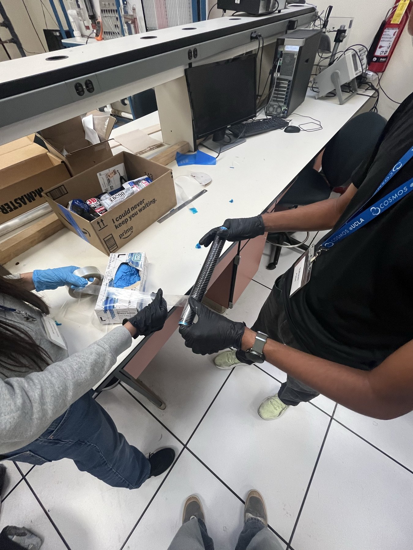
We decided to make our body out of carbon fiber. The body tube is a carbon fiber layup, as we wrapped carbon fiber sheets around an aluminum mandrel, let them cure, and then attempted to pull the tube off. Unfortunately, though, we hadn't left enough exposed mandrel and the carbon fiber basically fit 1:1 to the rest of the body tube, so we didn't have enough leverage to get the body tube off. Eventually, we had to split the body tube in half and use a coupler + epoxy to rejoin them.
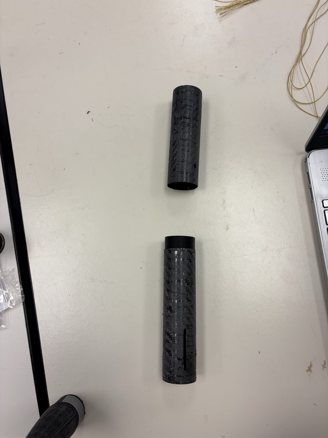
Printing and cutting
The nose cone, inner motor tube and assembly jig were 3D printed out of ABS. The fins and parachute holder were laser cut from 1/8 in. plywood. The first nose cone model had fillets that made it basically unprintable, which we caught the night before it went to the printer. The slots and holes in the carbon were done with a dremel.
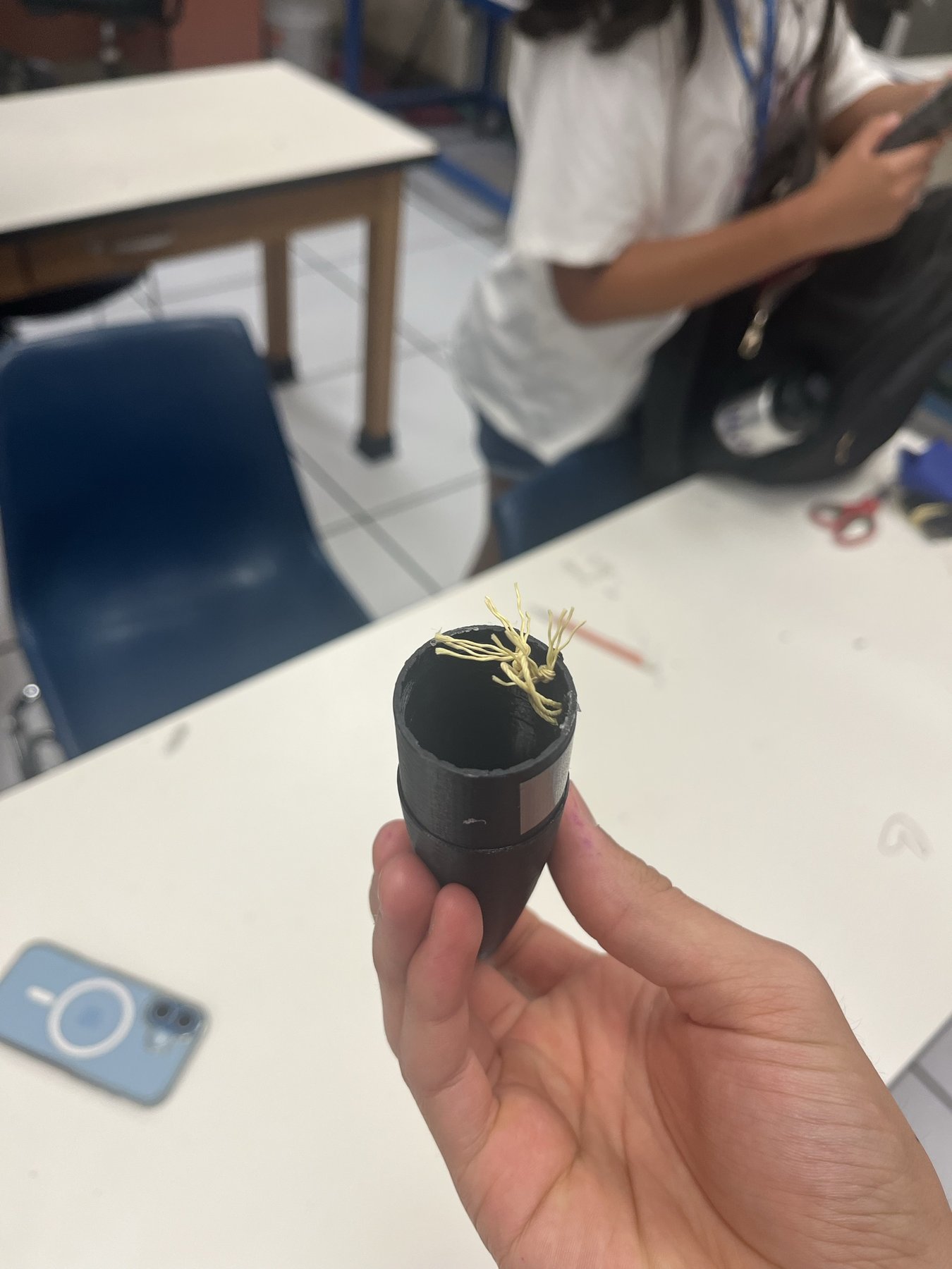
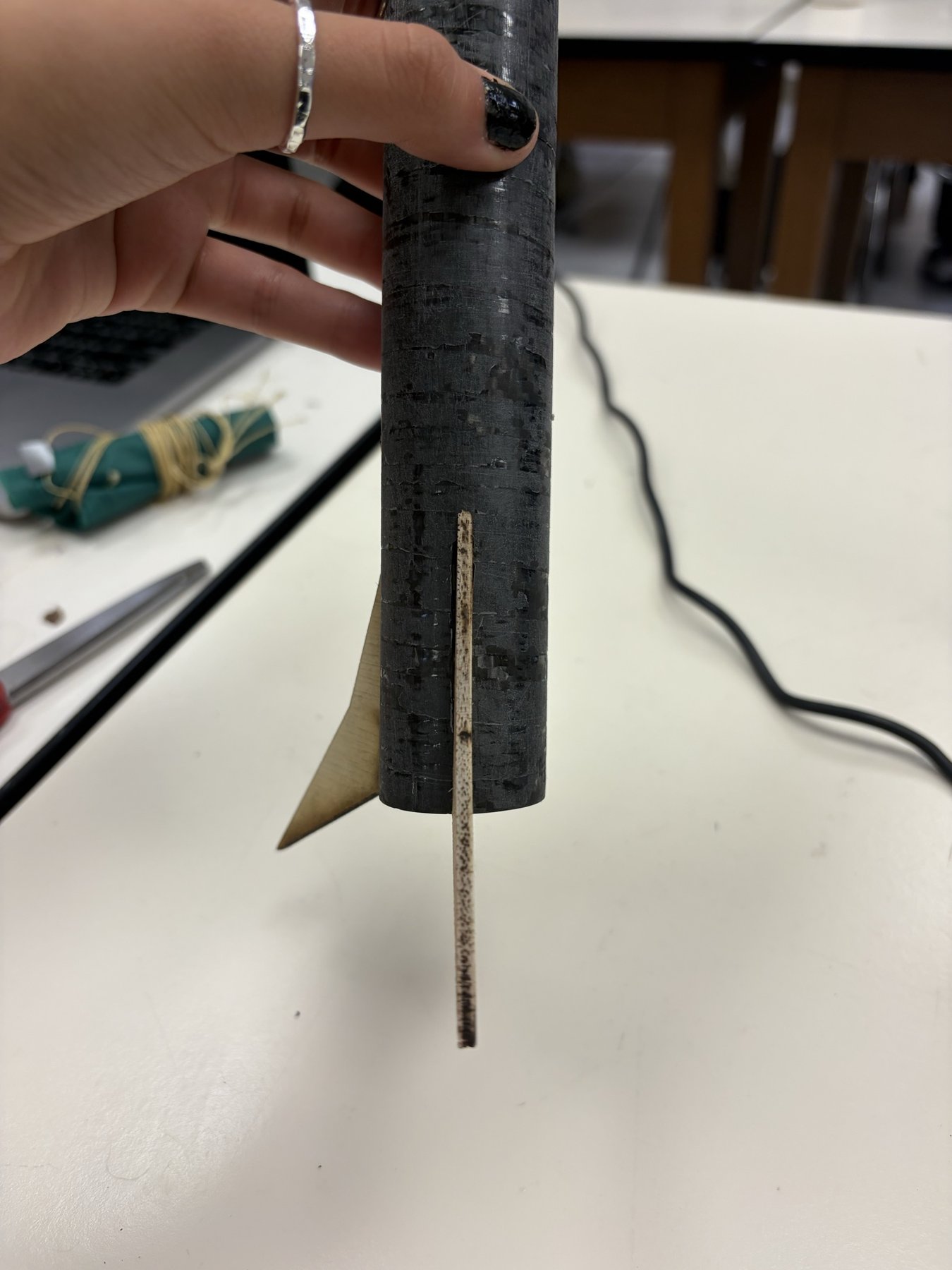
Protecting the egg
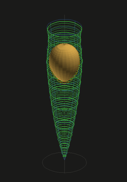
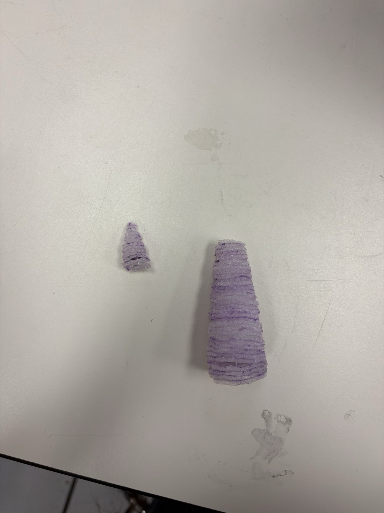
The egg sits in the nose cone inside a stack of foam layers, each one cut to fit the cone at that height with a hole where the egg goes. Cutting those by eye wasn't going to work, so our team made a tool to figure out the exact shapes we needed to cut out of foam in order to perfectly envelop the egg.
The inputs are two 3D models: the nose cone and the egg. The tool measures the inside of the cone, places the egg as deep as the foam walls allow, and then works its way up from the tip one foam sheet at a time. The output is a set of true-scale cutting templates, one for each layer, that we could print and cut straight from. Stacked together, the layers form a perfect mold of the cone with the egg inside it, so we could protect the egg without guessing at any of the shapes. It can also show each layer at real size on a monitor, so you can trace it onto paper without a printer.
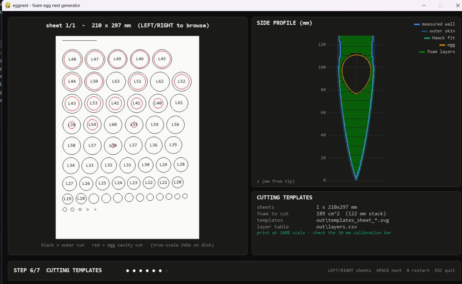
Parachute
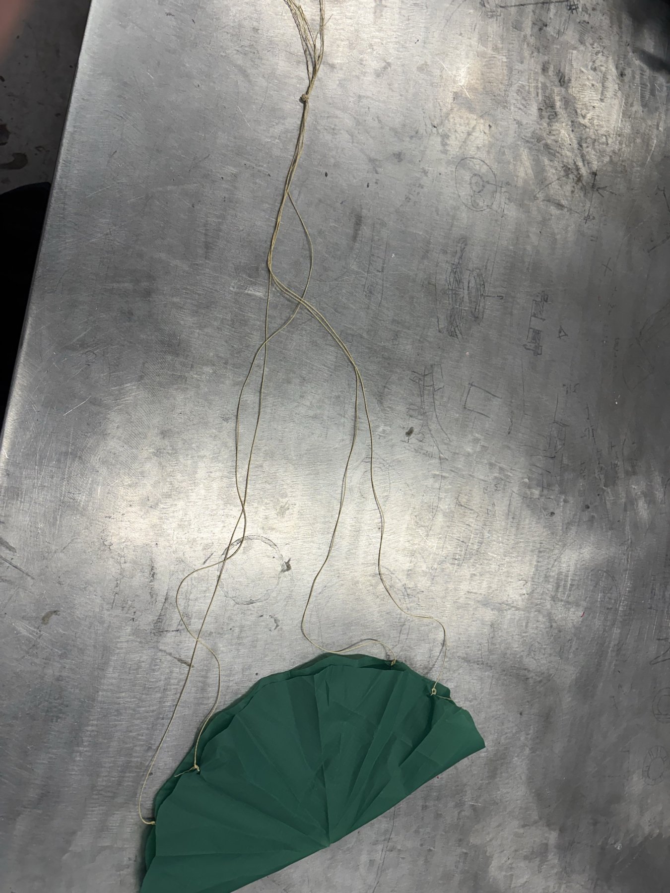
We sized the chute in OpenRocket and checked it with a descent-rate calculation in Desmos: a 15 in. canopy lands at ~17 ft/s, inside the 10–20 ft/s window we wanted, with a spill hole at the top so it doesn't swing. We drop tested it off the Engineering VI skybridge.
Wind tunnel
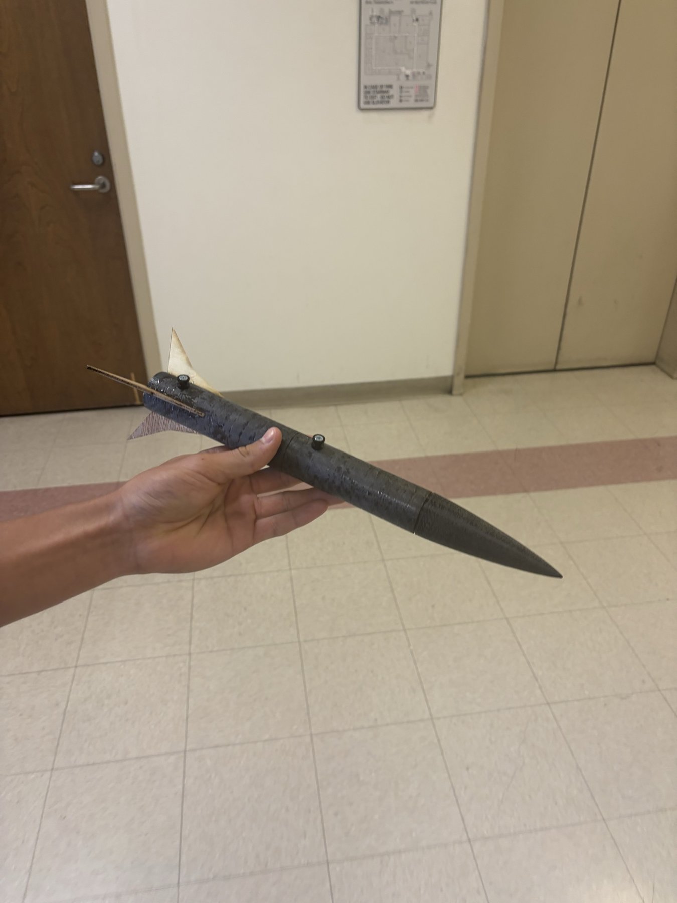
Before launch we tested the assembled rocket in the MAE wind tunnel to check that it tracked straight. At first it didn't, and the stability was pretty weak. As you can see in the video, it had some stability, but if it got pushed past roughly 20 degrees it would kick off sideways. In order to fix this, we added more glue into the nose cone, which moved the center of gravity forward.
Fixing the OpenRocket simulation
As a side note, once the rocket was built we re-measured it with its real mass and finished components and updated the simulation. With the new numbers, the predicted apogee shifted down from 1126 ft to 965 ft.
Launch, July 17
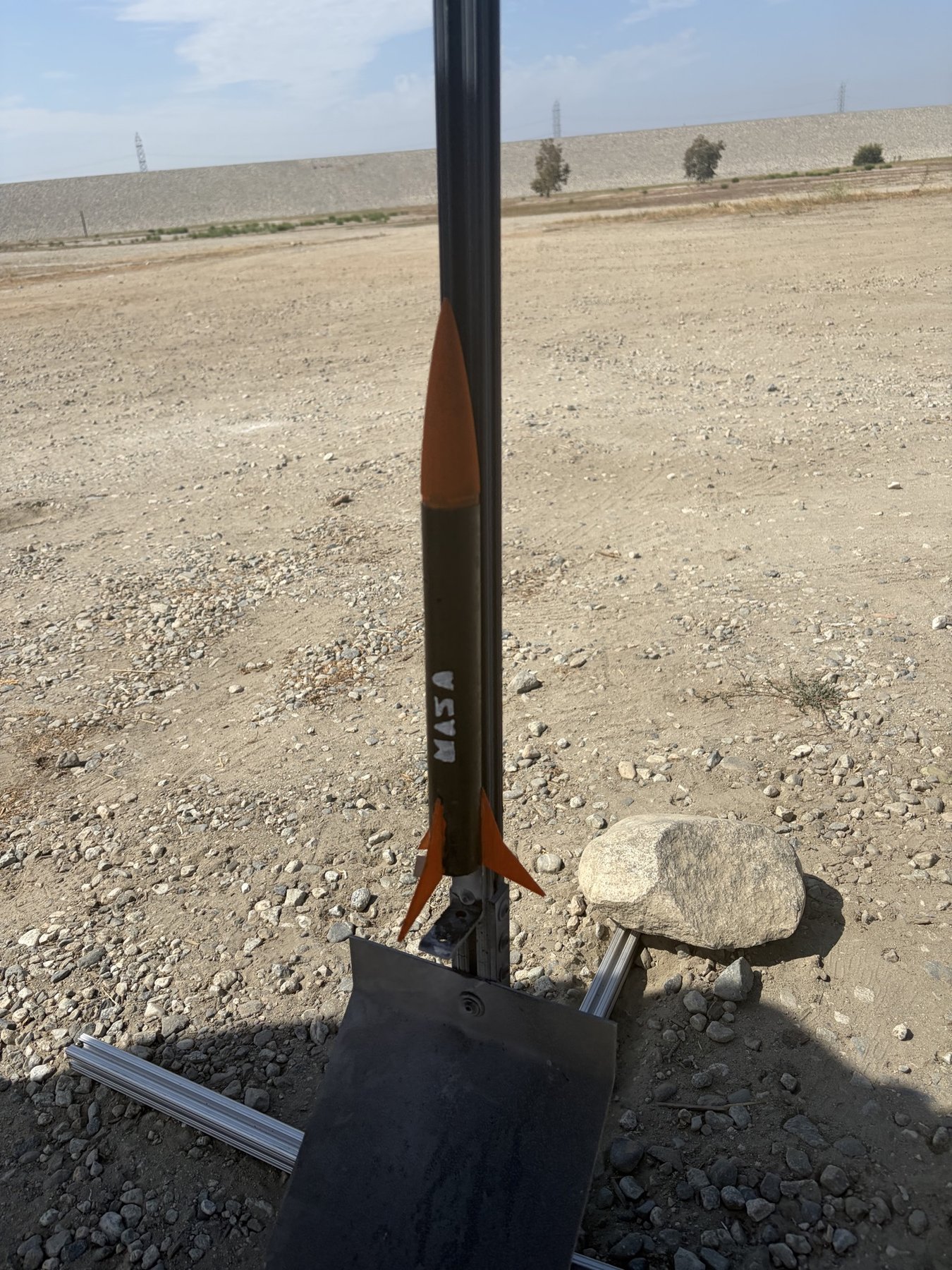
We launched at the Santa Fe Dam launch site, the supervised model rocket launch field at the Santa Fe Dam Recreation Area in Irwindale, California. There we put everything into our rocket and made it launch-ready for the first time, including burn paper, the altimeter, the actual egg, and the D12-5 motor.
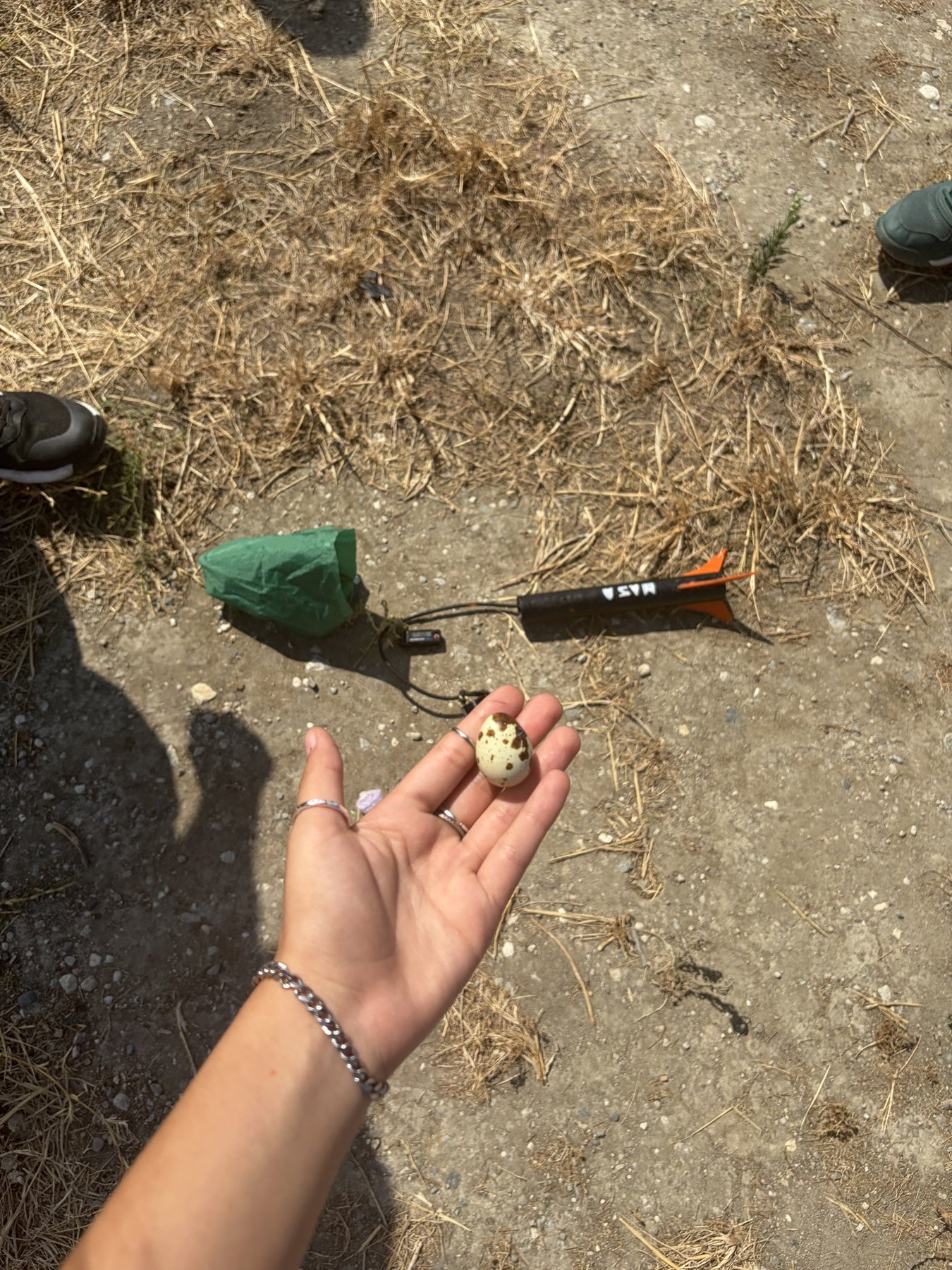
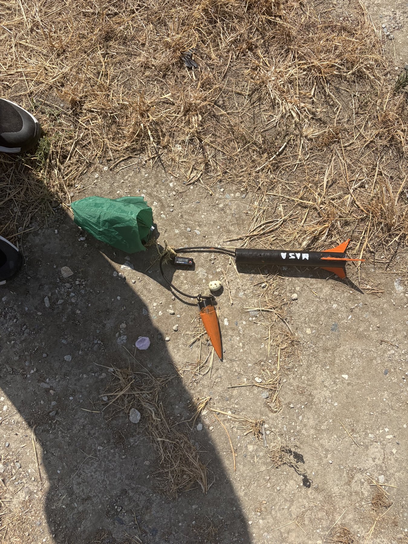
It went straight off the rail and the altimeter read 950 ft, the highest in Cluster 5 that year. The parachute didn't deploy correctly, so it came down at ~31 ft/s instead of 17 and the whole flight took 36.7 s instead of the predicted 55. The egg was fine, which I think is the foam layers doing their job.
Predicted vs. measured
| OpenRocket (design file) | OpenRocket (poster) | Measured | |
|---|---|---|---|
| Apogee | 965 ft | 1126 ft | 950 ft |
| Max velocity | 273 ft/s | 291 ft/s | 218 ft/s |
| Max acceleration | 573 ft/s² | 593 ft/s² | 183 ft/s² |
| Flight time | 54.8 s | 77.9 s | 36.7 s |
| Descent rate | 22 ft/s | 17 ft/s | 31 ft/s |
These files contain different design iterations. The measured flight differs from both simulations; the available data does not establish the cause of every difference.