This is my full presentation and live demo of the arm from February 2026.
draw on the paper · drag to orbit the arm runs the real IK at one waypoint per 25 ms
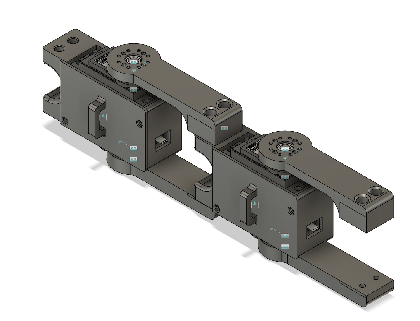
The model above is my actual Fusion 360 assembly, and its joints are driven by the same inverse kinematics as kinematics.py. You can draw on the paper and the arm will trace your drawing. The dots show every point on the paper the arm can reach, and the range of motion button shows the full space it can reach in 3D. The CAD doesn't include a gripper, so the arm ends at the mounting plate, which is the point the inverse kinematics measures to.
Why an arm
I started this in ninth grade with almost no robotics experience. I didn't want to buy a kit because I wanted the learning experience, so I built it from scratch and used it to teach myself. Along the way I learned CAD, 3D printing, wiring, PWM and serial, and enough math to figure out how to tell the arm where to go and have it actually move there. The whole thing came out to roughly $100 in parts.
Here it is tracing a scripted semicircle at two different heights with fun_path.py in January 2026.
Hardware
The arm uses five MG996R servos, one each for the base, shoulder and elbow and two for the gripper. They're all connected to a PCA9685 16-channel PWM driver over I²C, so the Arduino only has to read the serial commands and pass the angles along. The servos run off their own adjustable 5–6 V supply instead of the Arduino's power rail, since five MG996Rs pull more current than the board can provide. All of the structural parts are 3D printed, with heat-set threaded inserts and bearings at the joints.
In this video I walk through the hardware, including the box that holds the Arduino and the PCA9685, the base bearing, and the two joint assemblies.
Hold the printed parts together and keep the joints steady
The full assembly is in the repo as a STEP file (hardware/CAD/Full Assembly.step), and the model at the top of this page is made from that file.
Inverse kinematics
The solver takes a target position (x, y, z) and turns it into three servo angles. I worked it out on paper using the law of cosines, first a circle for the base and then the triangle formed by the two links, instead of using a library. The solver function in kinematics.py is about 30 lines of code, or 77 lines with my comments.
First, subtract the 50 mm base height so the origin sits at the shoulder pivot.
Project the target onto the ground to get r = √(x² + z²), and reject any target where z < 0.
Find the base angle from the chord between the target and the +x axis on that circle, then remap it to the servo's 0–180° range.
Find the shoulder angle with θ₁ = atan2(y, r) + acos((L₁² + a₃² − L₂²) / 2L₁a₃) + 60°, where a₃ is the distance from the shoulder to the target.
Find the elbow angle with θ₂ = acos((L₁² + L₂² − a₃²) / 2L₁L₂) − 90° + 60°.
If any angle comes out outside 0–180°, the point is unreachable and the function returns False.
The 60° is a homing offset. The shoulder and elbow servos are mounted rotated, so the useful range of the arm sits in the middle of each servo's travel. The base angle is also measured from the right side, which is 180° on my robot, and that's why the code subtracts it from pi.
There are two layers to the software stack of this project. On the laptop, Python performs the inverse kinematics and sends the joint angles over serial at 9600 baud in the packet format base j1 j2 g1 g2. There's also a pygame controller that lets you drive the robot and move the x, y and z position of the end effector. On the Arduino, a small C++ firmware reads each packet, splits it into the individual angles, and maps each one to a servo pulse width with its own calibration offset. When it boots, every servo homes to 90° so the arm always starts from a known pose.
To map out the workspace, a brute-force script runs a 10 mm grid of the workspace through the solver and dumps every reachable point to JSON. The reachable region on the paper at the top of this page uses the same idea, recomputed in the browser.
Timeline
May–Jul 2025 I wrote the first firmware, tested the servos, and found some code I thought I had lost.
Dec 2025 I added homing on boot and per-servo offsets, published the CAD and parts list, and moved the kinematics code into the main repo.
Jan 2026 I added the gripper and the pygame controller, fixed some mechanical issues, and recorded the path demo.
Feb 2026 I recorded the full presentation and live demo.
Build log, May–June 2025
May 16, 2025
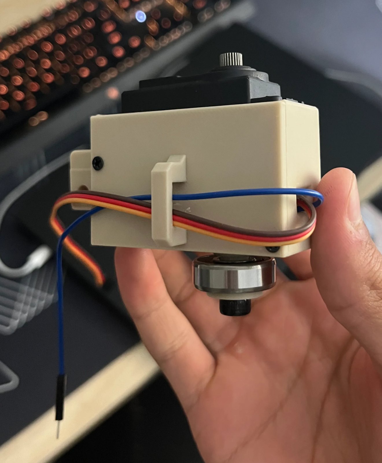
At this point I had a basic serial protocol on the Arduino, a servo housing that acts as a joint, a PCA9685 driver and MG996R servos. I soldered a pin to the potentiometer inside one servo and got it to read back its own angle. The things I still needed to work on were making the clearances fit my printer better, figuring out the best print orientation, and designing the arms for the joint.
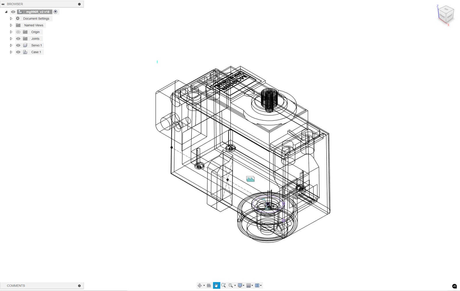
This is the first joint. The blue wire is the tap I soldered onto the potentiometer.This is the servo housing in Fusion 360.
June 1, 2025
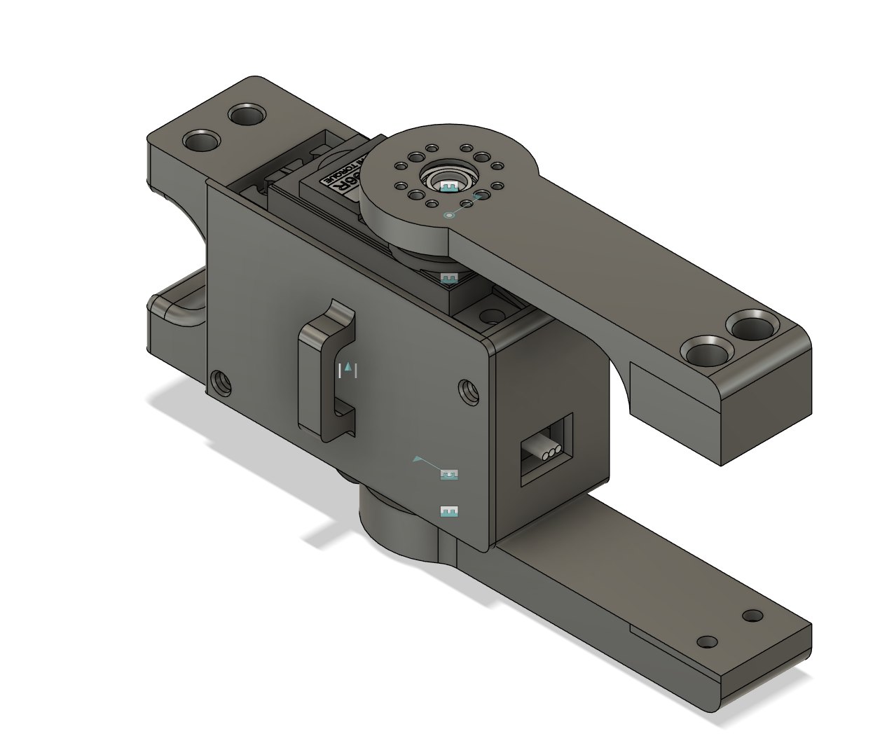
The case of the joint had a slant that I had hoped would not come back to bite me, but it did. I never used the project tool in my sketches, so the dimensions didn't line up with the servo model, and the very first extrude was on a slanted face of a servo model I found online. I ended up nuking the design and restarting, which also let me fix the joint-to-joint attachment, since that part wasn't well thought out. I wasted a lot of filament on test prints because I didn't think hard about the screw holes before printing. After that I joined the joints together in Fusion, ordered more parts from AliExpress because I had run out, and built it. I also learned about parametric parameters a little too late.
This is the redone joint with its connectors.These are two joints linked together, which was my first assembly in Fusion.
Here it is built, before I had made the base.
June 9, 2025
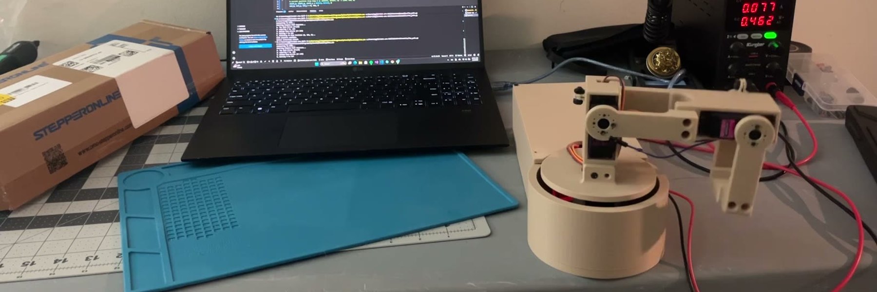
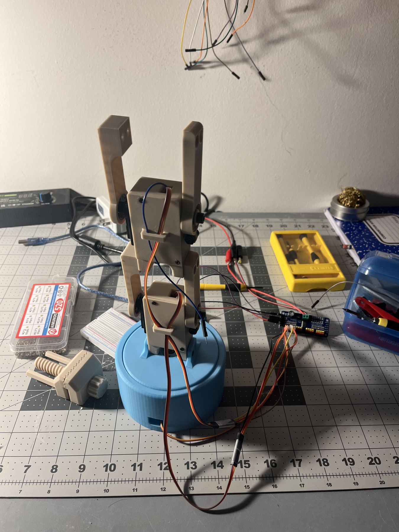
By this point I had finished the base, which is a simple circular base that houses one servo and connects to the upper joints (it could definitely be improved). I connected all of the servos to the Arduino and could move the arm over serial. The electronics still needed a lot of work, since I didn't know much about electronics yet.
This is the first full arm, wired up. I later replaced the blue base with the enclosure.This is the first time I moved it over serial.